Hardware setup
We are building up two hardware devices (stations). One is the base station, that could be located into your house. A LCD shows the data. The other is the remote inverter station, that is located e.g. in your shed, where the solar modules are mounted and the battery is used e.g. for charging your e-bike via a Waeco SinePower inverter.
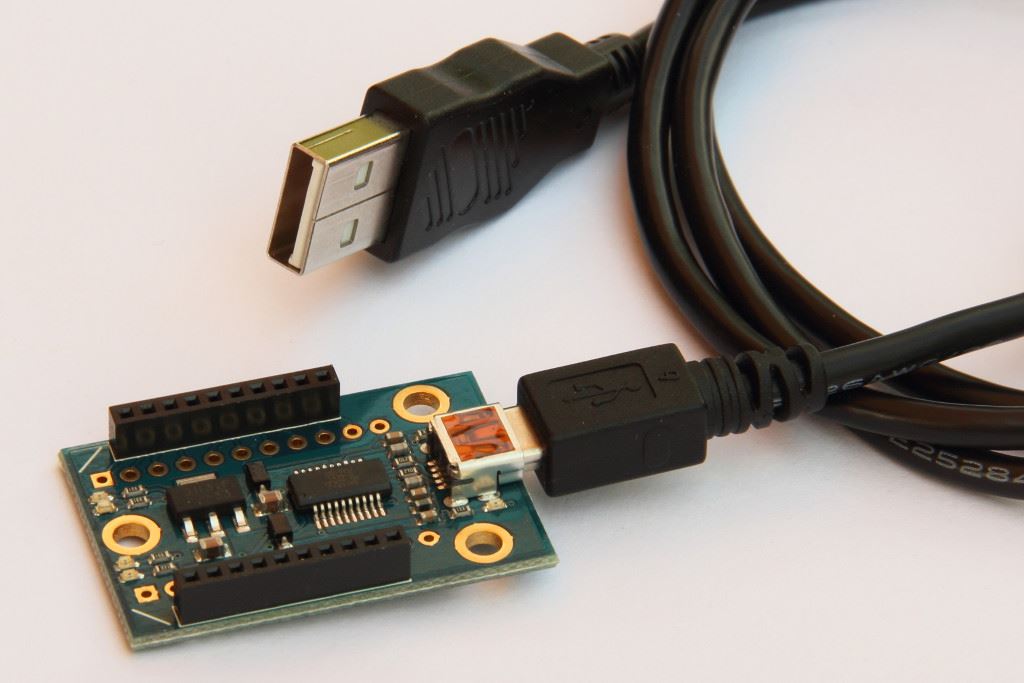
Programming the XBEEs
Base station with LCD
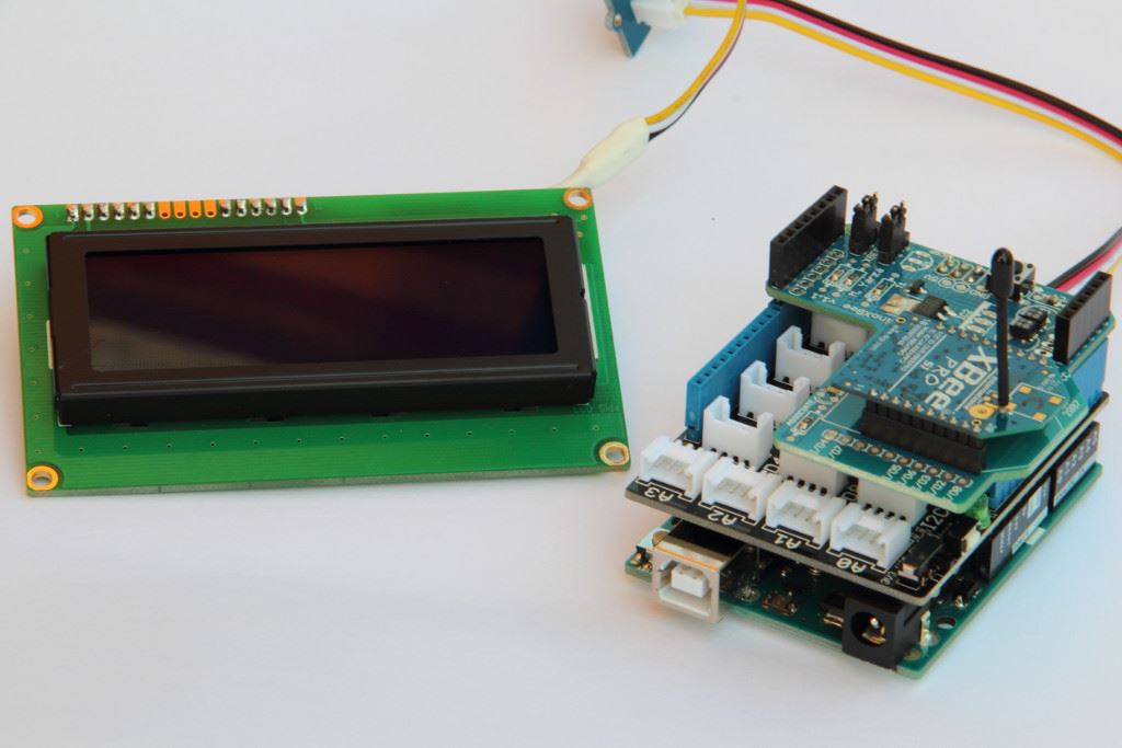
For building the base station you'll need:
Arduino XBEE shield (I used this old simple one from Libellium) but you could use the new Arduino Wireless SD shield as well.
XBee Pro - 10mW with Wire Antenna - Series 1 - XBP24-AWI-001J ("Series 1" is main criteria!, Choose antenna you like.)
LCD 4 x 20 characters, attached to the I2C bus (bought this chinese YWRobot thing and downloaded the library there)
The grove shield is optional. Only used to attach the display with nice connectors - made a little cable.
While setting it up, the Arduino is powered via USB, afterwards a 12 VDC power adaptor could be fine.
Stack the XBEE shield onto the Arduino Uno R3. Stack the XBEE onto the XBEE shield.
The Jumpers of the XBEE shield have to be positioned at "USB" before uploading a new program to the Arduino. For XBEE usage, they have to be changed to "XBEE". This is a must since we do use the same serial interface for uploading programs and XBEE communication.
Remote inverter station

For building the remote inverter station you'll need:
RS-232 shield - Attention: the print on the board is wrong: "232_TX" and "232_RX" have to be exchanged otherwise TX-LED is blinking when receiving data, RX is blinking when your Arduino is sending data (take a look at the schematic and it will be obvious). Regarding to the print on the RS-232 shield, jumper pin 2 as "232_RX" and pin 3 as "232_TX". May be the manufacturer corrects this ome time. At my board it's written "232_TX" then below: "Digital" then below "232_RX".
Arduino XBEE shield (I used this old simple one from Libellium) but you could use the new Arduino Wireless SD shield as well.
XBee Pro - 10mW with Wire Antenna - Series 1 - XBP24-AWI-001J ("Series 1" is main criteria!, Choose antenna you like.)
While setting it up, the Arduino is powered via USB, afterwards a 12 VDC power adaptor could be fine.
Stack the RS-232 shield onto the Arduino, stack the XBEE shield onto the RS-232 shield, stack the XBEE onto the XBEE shield.
The Jumpers of the XBEE shield have to be positioned at "USB" before uploading a new program to the Arduino. For XBEE usage, they have to be changed to "XBEE". This is a must since we do use the same serial interface for uploading programs and XBEE communication.
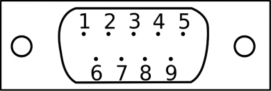
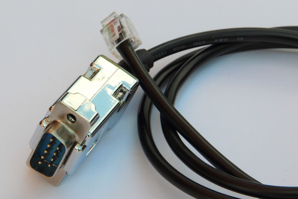
For building the inverter communication cable you'll need:
DB-9 male connector (commonly used for RS-232).
Housing for the DB-9 connector to secure the welding connections.
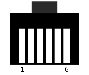
RJ-12 connector (6 lines) - this is needed to get contact to the WAECO MSI remote plug. I recommend to find a cable where it is already attached, then cut the cable at desired length and attach the DB-9 there.
|
DB-9 (RS-232) |
RJ-12 (Western) | |
|
| |
|
2 (RXD) |
<--> |
3 (RXD) |
|
3 (TXD) |
<--> |
4 (TXD) |
|
5 (GND) |
<--> |
2 (GND) |
Only these three lines are to be connected (see table).
A line in the table is one 1:1 connection. Don't cross RX with TX or so. Don't be creative here.
That's the hardware, now we will have a look at the programming of the both stations.