Serial Protocoll WAECO SinePower MSI
The technical documentation department of Dometic dent me the necessary protocol to talk to the SinePower MSI inverters.
So this is the description, how the Arduino RS-232 shield talks to the inverter.
For communication the byte structure is as follows: Baud rate 4800, 8 Bit of data, no parity, one stop bit.
Each command has to end with CR (0Dh) and LF (0Ah) which is done by Arduino with the "SPW.println()". After the inverter has executed the command, it will send back a response string. If data is transmitted from the inverter to the Arduino, the data is sent and afterwards the response string is sent, too.
Response strings
"=>" followed by CR LF: Command executed successfully
"!>" followed by CR LF: Command correct but execution error (e.g. parameters out of range)
"?>" followed by CR LF: Command error, not accepted
Since we do know, how a command has to look like and have tested all the needed commands, we use only the "=>" for being sure, that the command was executed.
Remember! Each command has to be sent with a CR LF after it.
Commands
|
Power <value> |
Values could be "0" = Power Off or "1" = Power On. This command has no effect in switching on/off the inverter. I talked to the head of electronics department, who told me, that this switches on/off the inverters' power saving mode. I have not tested it, because I never want the power saving mode. Within power saving mode, the inverter sends out a little impulse and measures the power needed by the output. If the power is below the configured threshold, the power saving remains active. So using power saving mode could be dangerous when having a fridge connected to the output. When saving power (fridge off), the test impulse is sent out, measures only the consumption of the fridges' electronics and sleeps further. The fridge will never be powered then ... A simple bulb connected to the output will consume the power of the test pulse, the power saving mode will be left. |
|
FRQ? |
Output frequency of the inverter. |
|
VINV? |
Output voltage of the inverter. |
|
IINV? |
Output current of the inverter. |
|
PINV? |
Output power of the inverter. |
|
VBAT? |
Battery voltage = input voltage of the inverter. |
|
*RST |
Reset the inverter. (I have not tried this.) |
|
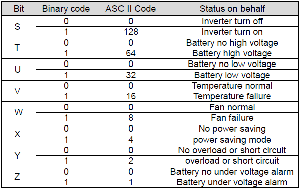
STA? |
Status of the inverter. See table below. |
The protocol also offers the setting of configurations: overvoltage protection, overvoltage recovery, undervoltage protection, undervoltage recovery, undervoltage alarm, output voltage, RS 232 baud rate, output frequency, shutdown retry. All of these are either set as default correctly or are set once by the user to different values. So there is no need to change these on-the-fly remotely.
Maybe I'll add these 2 DIN A4 pages as well some time.